Getting Started
Base software installation and configuration
Steps
- Install Nodejs and NPM
- Install Node-RED
- Install Node-RED Ethernet/IP
- Install Node-RED Dashboard (Optional)
Installing Nodejs, NPM and Node-RED
Detailed installation instructions for multiple operating systems are available on the Node-RED site
- Windows
- Raspberry Pi and other Debian based linux installations such as Ubuntu (Preferred)
- RPM Based Linux install scripts such as Red Hat, Fedora, CentOS, Oracle Linux
- Other Install Methods
Install Node-RED Ethernet/IP module
Go to Node-RED directory usually:
cd $HOME/.node-red
Install Ethernet/IP node to Node-RED palette:
npm install @serafintech/node-red-contrib-eip-io
Launch Node-RED
Run this command to start Node-RED
node-red
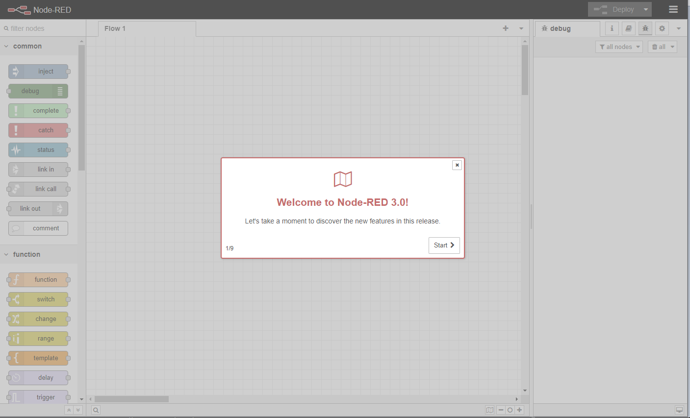
After start up , open up your browser and go to http://localhost:1880/.
You should see something like this.
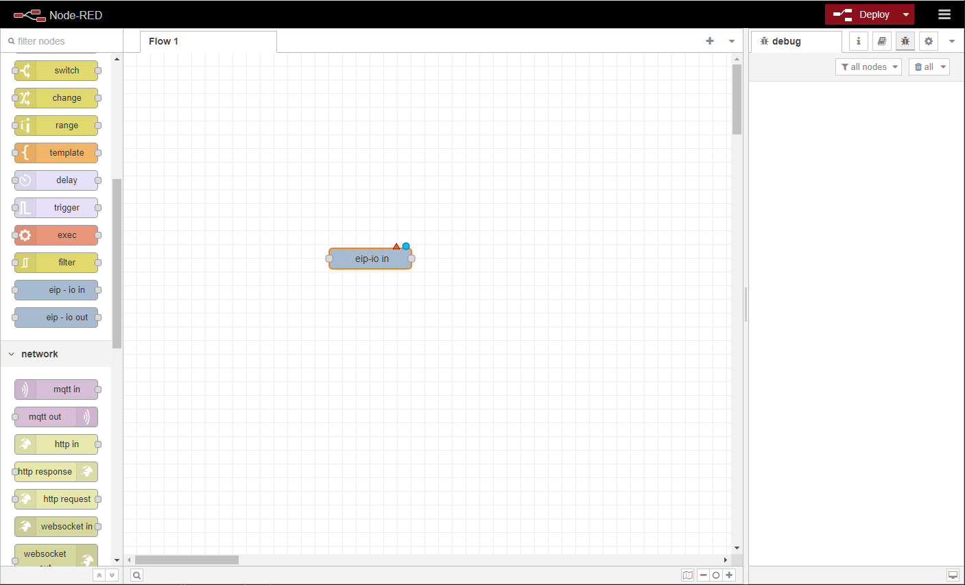
Adding a Ethernet/IP Device
Drag and drop an eip-io in node on to the flow.
Double click on the new eip-io in node to open up its parameters. Click the edit button at the Connection property to add a new connection node.
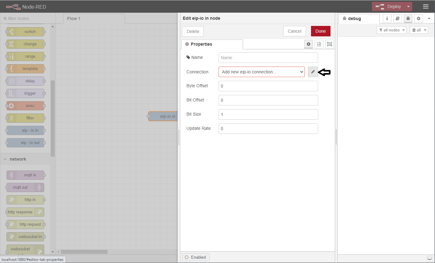
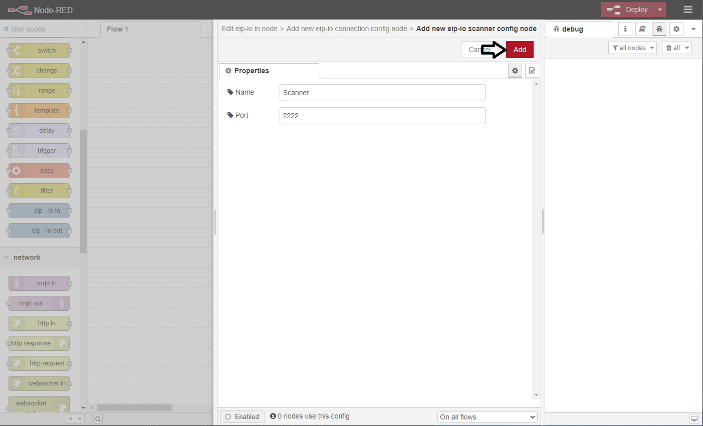
Now click on the edit button at the Scanner property to add a new scanner node.
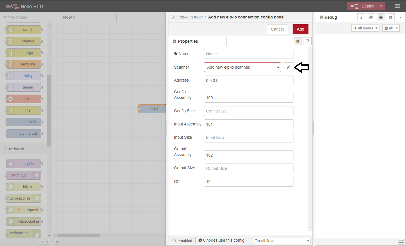
Here you will use the default properties for the scanner node and click Add.
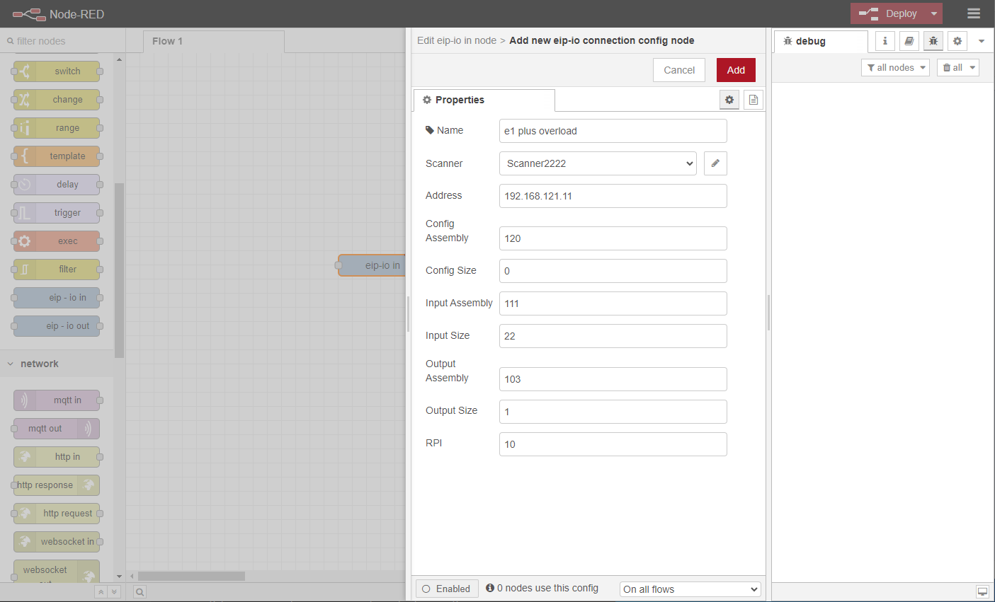
This will bring you back to the connection node setup where you can see the Scanner property selected is the newly created scanner node. Next you need to fill in the rest of the connection properties.
- Name
- Names the connection. The device in the example is an Allen Bradley E1 Plus overload relay.
- Address
- The IP address of the device.
- Config Assembly
- From manufacturer's documentation.
- Config Size
- In 8-bit bytes. From manufacturer's documentation.
- Input Assembly
- From manufacturer's documentation.
- Input Size
- In 8-bit bytes. From manufacturer's documentation.
- Output Assembly
- From manufacturer's documentation.
- Output Size
- In 8-bit bytes. From manufacturer's documentation.
- RPI
- Delay between messages to/from device in milliseconds. 8ms minimum.
And then click Add.
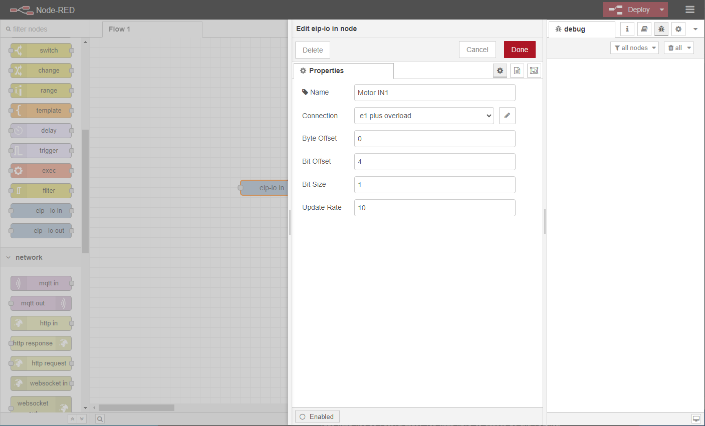
Now back to the input node, the rest of the parameters can be entered. The example uses the table from the manufacturer (below) to setup the input node as Input 1.

- Name
- Names the node.
- Byte Offset
- Number of 8-bit bytes to skip on the input assembly.
- Bit Offset
- Number of bits to skip on the input assembly.
- Bit Size
- Number of bits to read from the input assembly.
- Update Rate
- The input node will check for changes in value at this rate in milliseconds. If the value has changed, a new message will be sent from the node containing the new value. If this is set to zero, a message containing the current value will only be sent if the node receives an input message from another node.
Click Done To complete setup of eip-io in node.
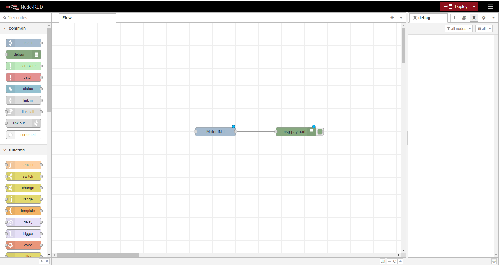
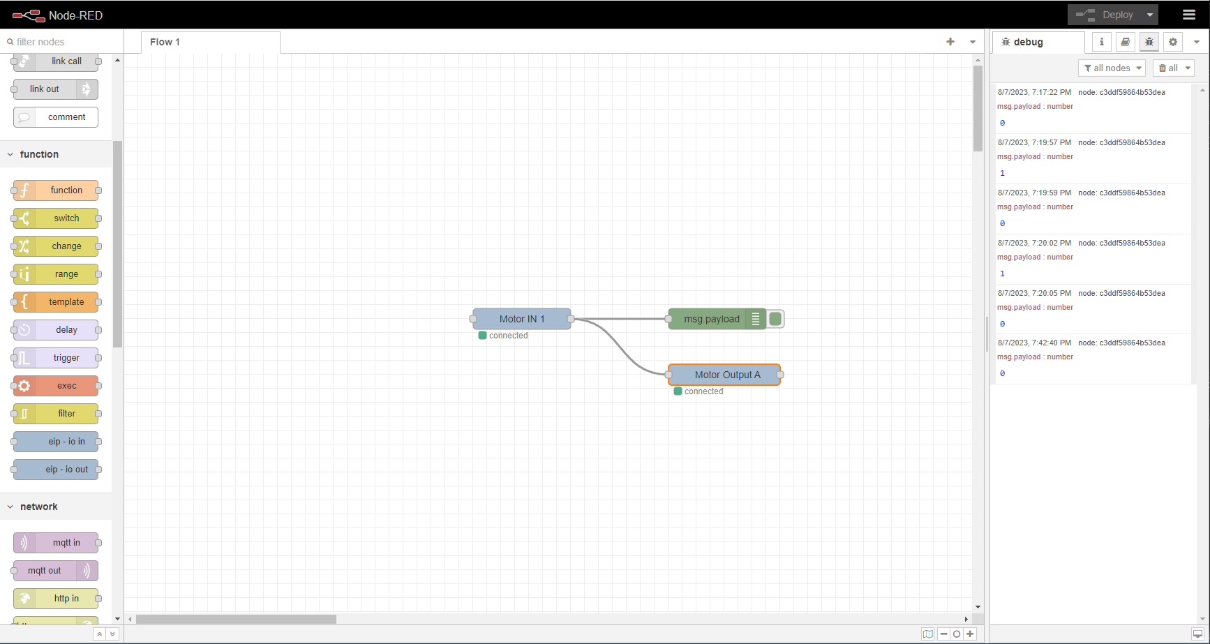
Node Completed.
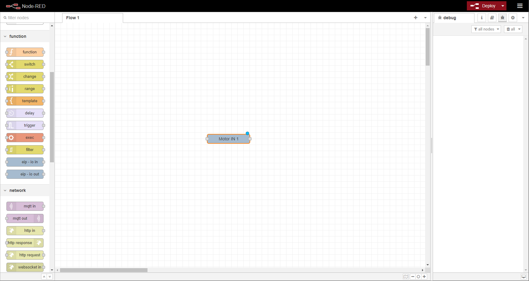
A Debug node was added and the output from the Motor IN 1 is connected to the input of the Debug node so that the Motor IN 1 can be monitored.
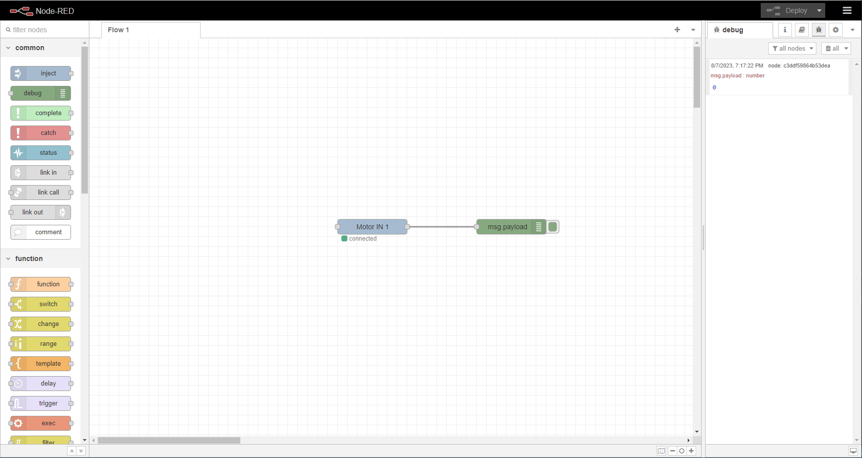
Now click deploy and the Motor IN 1 node will show connection status. The Debug output will show the initial value.
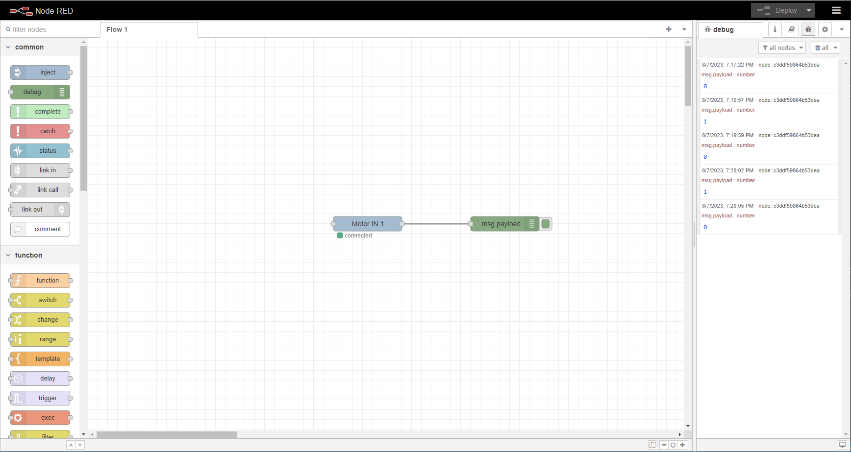
A pushbutton switch is hardwired to the device and turned on and off to demo the function of the node.
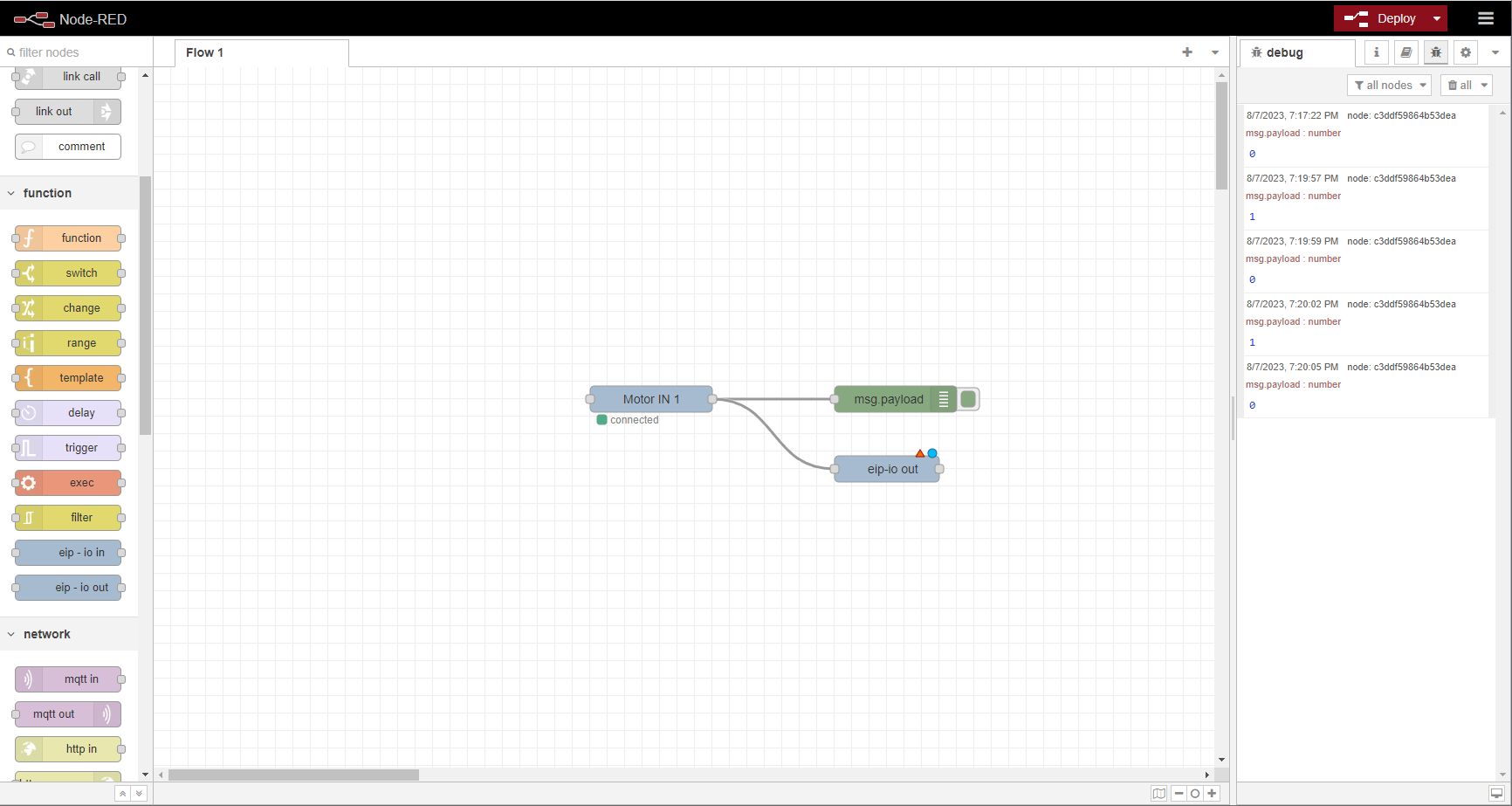
Next an eip-io out is added. The Motor IN 1 is connected to the eip-io out so when the button is pushed it will turn on the output.
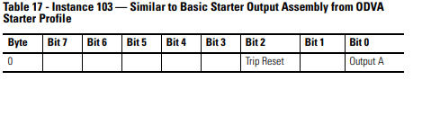
A table from the manufacturer's documentation describes the output mapping.
When setting the properties of the eip-io out, we re-use the same connection node by selecting it from the drop down.
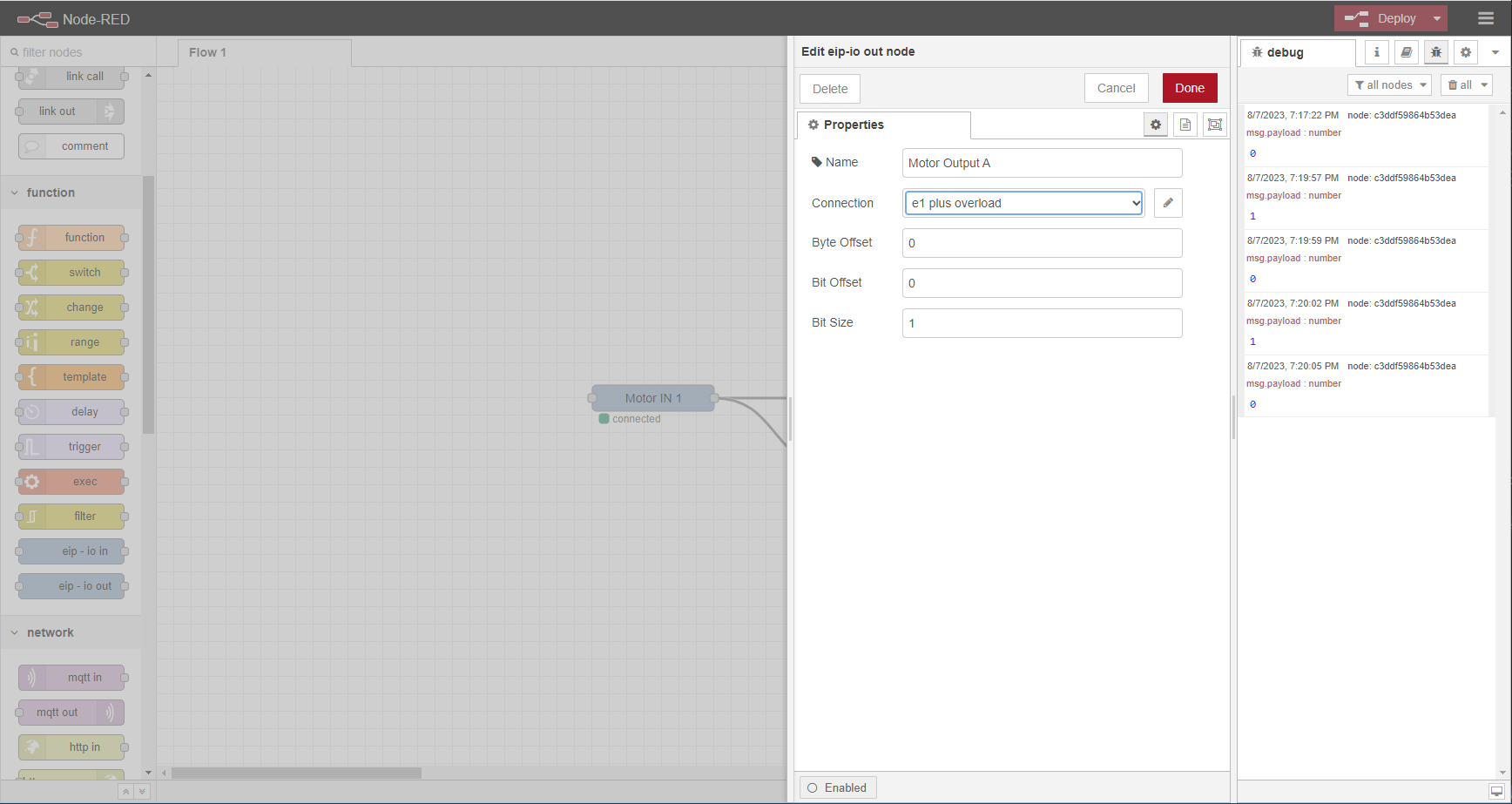
Click Done and then Deploy and now the output relay of the E1 Plus turns on and off with the push button.
See Node-RED user guide for more information on programming in Node-RED